


1. 557-7627 HEUI Injector Technical Support
1.1. 557-7627 HEUI Injector Application Scenarios
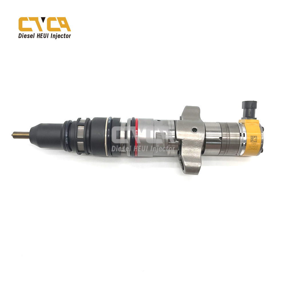
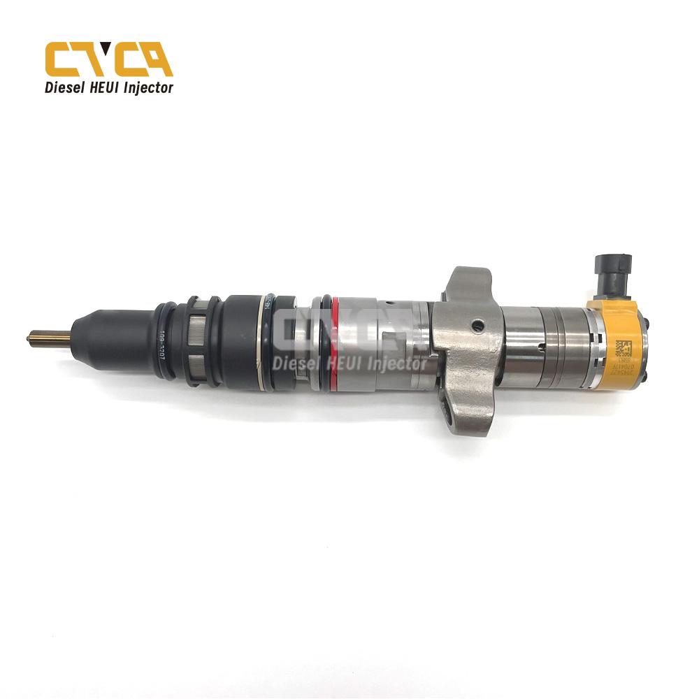
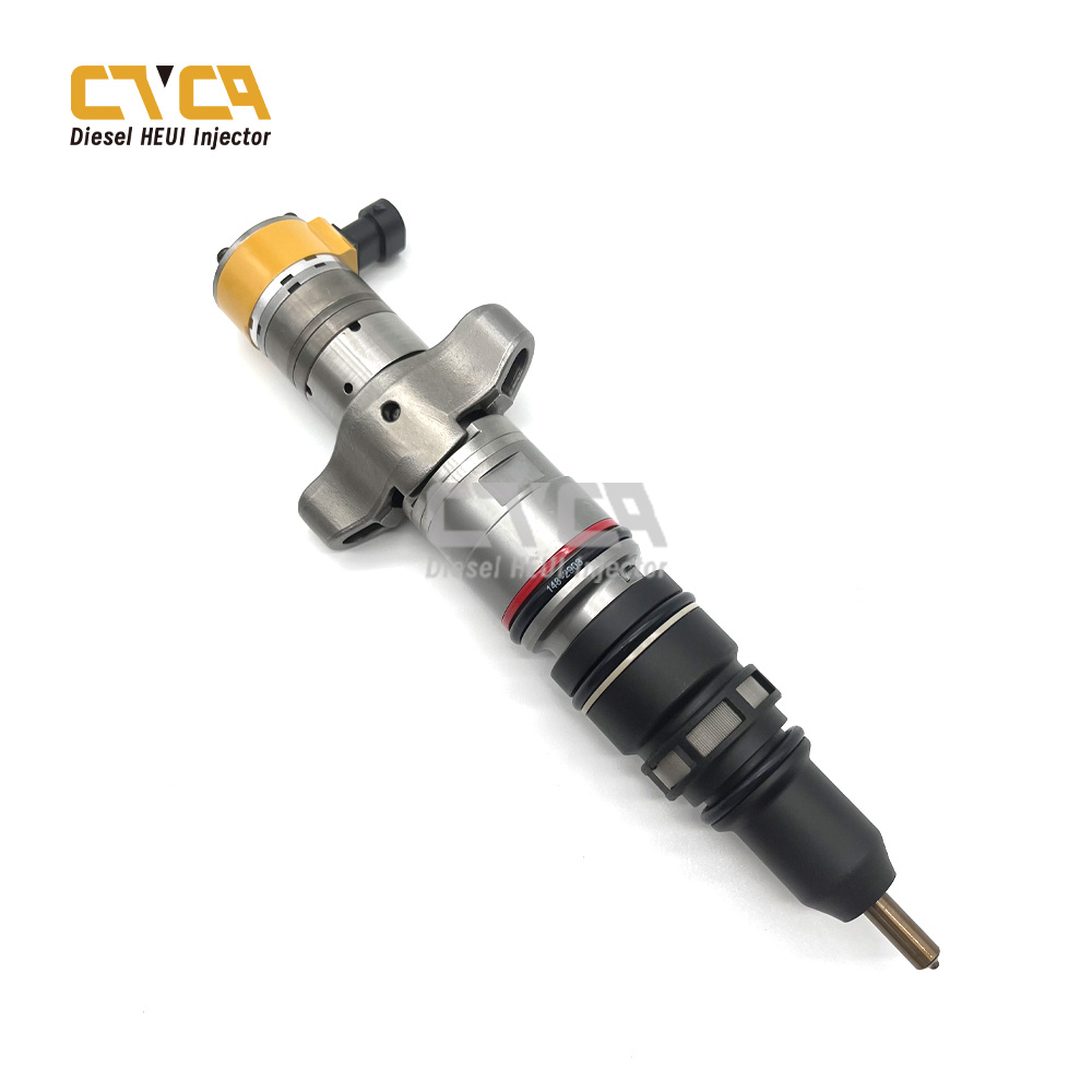
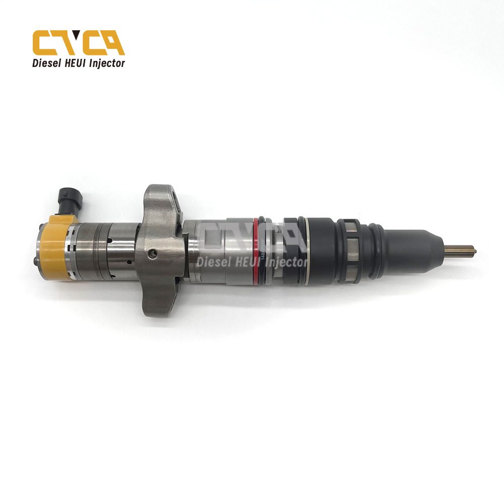
557-7627 HEUI injector suitable for C7 engines car model, and it’s application scenarios shows as follows:

1.2. 557-7627 HEUI Injector Tool Instruction Manual
(1)Injector Nozzle Nut Disassembly And Assembly Wrench
It is mainly used to remove the nozzle nut when it is too tight or difficult to loosen. If the nozzle nut cannot be loosened, place the nozzle nut on the platform and use a copper hammer to gently tap the threaded end and the small end of the nozzle nut. The tightening torque when tightening the C7/C9 injector nozzle nut is 100 N/m. When tightening the C-9 injector nozzle nut, the tightening torque is 80 N/m.
(2)Injector Splint
It is mainly used to quickly clamp the HEUI injector with the help of ordinary bench vise.
(3)Adapter
Install the HEUI injector assembly, diesel valve assembly and nozzle spring on the adapter according to the assembly sequence. Tighten them with the nozzle nut, and then test the opening pressure of the nozzle assembly. Test the speed of pressure relief, atomization status, whether there is dripping, whether the hole is blocked, whether it is stuck, etc. It is recommended to remove the oil seal and needle valve of the injector nozzle during testing.
The opening pressure of the C7/C9 injector is about 220ba, and the opening pressure of the C-9 is about 160ba.
(4)Piston Ring Installation Tools
Firstly, put the piston ring support ring on the guide sleeve, then put the guide sleeve on the convex end of the cleaned piston, then put the thrust sleeve on the guide sleeve, push the support ring gently to install the support ring in place, and then use the same method Just install the piston rings.
(5)Piston Ring Resetter
Due to the special nature of the material, the installed piston ring needs to be reset before it can be installed into the housing.
Slowly push the piston with the piston ring into the reset device and then pull it out to complete the reset. Be careful not to damage the piston ring.
(6)High-pressure Oil Seal Installation Sleeve
Put the installation sleeve on the injector without oil seal. Put the replaced high-pressure oil seal on the installation sleeve. Gently push the oil seal or support ring with your hand to put it in place. Pay attention to install the upper oil seal of the injector first and then install the middle oil seal.
(7)Oil Seal Driver
Remove the inner and outer oil seals for use.
(8)T10, T25 Torx Wrench
Disassemble and install the solenoid valve fastening bolts and the spool valve pressure plate fastening bolts.
(9)Grinding rod
Used when replacing the spool valve core and diesel balance valve core, remove the old valve core by grinding. Apply a little 10000 mesh (No. 0.5) grinding sound on the grinding rod, slide up and down and turn the grinding rod left and right to expand the inner hole and make it smooth to facilitate replacement of the oversized valve core.
(10)Stroke Measuring Tool (XCLG-04):
Used to measure armature stroke, total armature stroke, C7/C9 valve stroke, C-9 spool valve stroke.
①Total Armature Stroke Measurement
Clamp the oil control valve in a bench vise, be careful not to clamp it too tightly, and put the stroke adjustment pad (aluminum pad) on it. Clear the measuring tool with a flat surface and place it on the control valve assembly. At this time the measured stroke is the installation stroke, and the normal value is 0.235-0.250mm. If the stroke is wrong, replace the aluminum pad and adjust it. The total stroke parameters and measurement methods of the C7/C9/C-9 armature are the same.
②Armature Stroke Measurement
Place the measuring tool on the control valve assembly to clear it, and push it up with a 2-5m round rod. The normal value is 0.140-0.175mm. If it is out of range, it is recommended to repair or replace it. C7/C9/C-9 armature stroke parameters and measurement methods are the same.
③C7/C9 SpoolValve Core Movement Stroke Measurement
Place the spool valve assembly on a flat surface. Clear the tool on the flat surface and place it on the spool valve. The measured stroke is the spool valve stroke 1.490-1.510mm.If it is incorrect, you can replace the valve core or replace the spool valve partition for adjustment.
④C-9 Measurement of the Total Stroke of The SpoolValve Core Movement
Only install the valve core and shell and place them on the platform. Clear the measuring tool on the plane and then place it on the spool valve. The measured stroke at this time is the total stroke of the spool valve. The normal value is 2.100-2.200mm.If the total stroke of the spool valve is incorrect, replace the valve core and adjust it.
⑤C-9 Spool ValveCore Movement Stroke
⑥place the positioning pin one-way valve ball, one-way valve ball limit plate, and the spool valveassembly without spring on the shell in sequence (pay attention to the valve ballon the direction of the arc surface of the spool valve push rod), use this measuring tool to clear it on a flat surface and place it on the spool valve The measured stroke is the spool valve stroke. The normal value is 1.200-1.300mm. If the parameters are incorrect, change the length of the spool valve push rod to adjust.
(11)Stroke measuring tool (XCLG-01)
Used to measure the pre-installation height of solenoid valve and spool valve spring pre-installation height.
①Measurement of The Pre-installation Height of The Solenoid Valve Spring
Place the control valve assembly on the platform, and place the aluminum pad, solenoid valve spring pad, and solenoid valve in sequence. At this time, the spring is higher than the flat surface. The normal value of C7/C9 is about 1.650-1.730mm, C-9 normal value is about 1.750-1.830mm. If the pre-installation height is incorrect, just adjust the solenoid valve spring pad.
②Measurement of The Pre-assembly Height of the spool valvespring
Place the fully assembled spool valve assembly on the platform or the shell (C-9 should be placed on the shell). Clear the measuring tool on the flat surface and then place it on the spool valve. The measured height is the pre-installed height of the spring. The pre-installed height of C709 is 0.450-0.550mm, and the pre-installed height of C-9 is 3.450-3.550mm. If the measured height is incorrect, replace the spring and adjust.
(12)Stroke measuring tool (XCLJ-05)
Used to measure the nozzle needle valve stroke.
The needle valves of C7, C9 and C-9 are measured in the same way. Put the assembled injector assembly, injector partition, diesel valve assembly together with the injector spring and stroke limit pin into the needle valve stroke measuring tool. The stroke measuring tool is cleared on a flat surface and then placed on the spring end of the nozzle for measurement. The measured value is the nozzle needle valve stroke. The normal value is 0.250-0.270mm. When the stroke is not within the range, it can be adjusted by changing the length of the limit pin.
2. Copyright Statement
All content in this passage “557-7627 HEUI Injector Encyclopedia”, including but not limited to text, graphics, logos, images, and multimedia, is the property of www.heuiinjector.com and is protected by copyright laws. The content in this passage is intended for personal and non-commercial use. Any unauthorized use of the materials for commercial purposes is strictly prohibited and may violate copyright, trademark, and other laws. You are not allowed to modify, reproduce, distribute, or republish any of the content from this passage without prior written permission from www.heuiinjector.com. For inquiries regarding the use of any material, please contact us via hison@shumatt.com

